SSD1306 128X32
Вс фев 25, 2018 12:08:55
Доброе время , есть у кого датащит на SSD1306 128X32 , в интернете нахожу только на 128X64. И хоть Коды на них совместимы , изображение всегда уже в 2 раза.
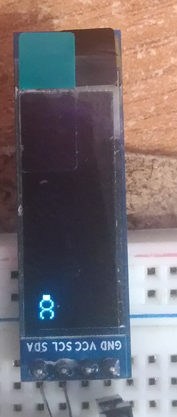
К примеру попробывал эту статью http://radiokot.ru/articles/77/ кот в 2 раза уже вышел , но с той же длинной . 3-ка вообще похожа на 8.
К примеру попробывал эту статью http://radiokot.ru/articles/77/ кот в 2 раза уже вышел , но с той же длинной . 3-ка вообще похожа на 8.
Re: SSD1306 128X32
Вс фев 25, 2018 14:04:06
не благодари)))
смотри внимательно инициализацию там в двух местах...
Спойлер
- Код:
#define OLED_DEFAULT_ADDRESS 0x78
#define OLED_SETCONTRAST 0x81
#define OLED_DISPLAYALLON_RESUME 0xA4
#define OLED_DISPLAYALLON 0xA5
#define OLED_NORMALDISPLAY 0xA6
#define OLED_INVERTDISPLAY 0xA7
#define OLED_DISPLAYOFF 0xAE
#define OLED_DISPLAYON 0xAF
#define OLED_SETDISPLAYOFFSET 0xD3
#define OLED_SETCOMPINS 0xDA
#define OLED_SETVCOMDETECT 0xDB
#define OLED_SETDISPLAYCLOCKDIV 0xD5
#define OLED_SETPRECHARGE 0xD9
#define OLED_SETMULTIPLEX 0xA8
#define OLED_SETLOWCOLUMN 0x00
#define OLED_SETHIGHCOLUMN 0x10
#define OLED_SETSTARTLINE 0x40
#define OLED_MEMORYMODE 0x20
#define OLED_COLUMNADDR 0x21
#define OLED_PAGEADDR   0x22
#define OLED_COMSCANINC 0xC0
#define OLED_COMSCANDEC 0xC8
#define OLED_SEGREMAP 0xA0
#define OLED_CHARGEPUMP 0x8D
#define OLED_SWITCHCAPVCC 0x2
#define OLED_NOP 0xE3
- Код:
void OLED_init(void)
{
      i2c_init();

      // Turn display off
      sendCommand(OLED_DISPLAYOFF);

      sendCommand(OLED_SETDISPLAYCLOCKDIV);
      sendCommand(0x80);

      sendCommand(OLED_SETMULTIPLEX);
      sendCommand(0x1F);//128x32
      //sendCommand(0x3F);//128x64

      sendCommand(OLED_SETDISPLAYOFFSET);
      sendCommand(0x00);

      sendCommand(OLED_SETSTARTLINE | 0x00);//0

      // We use internal charge pump
      sendCommand(OLED_CHARGEPUMP);
      sendCommand(0x14);

      // Horizontal memory mode
      sendCommand(OLED_MEMORYMODE);
      sendCommand(0x00);

      sendCommand(OLED_SEGREMAP | 0x1);

      sendCommand(OLED_COMSCANDEC);

      sendCommand(OLED_SETCOMPINS);
      sendCommand(0x02);//128x32
      //sendCommand(0x12);//128x64

      // Max contrast
      sendCommand(OLED_SETCONTRAST);
      sendCommand(0xCF);//0xCF

      sendCommand(OLED_SETPRECHARGE);
      sendCommand(0xF1);

      sendCommand(OLED_SETVCOMDETECT);
      sendCommand(0x40);//0x40

      sendCommand(OLED_DISPLAYALLON_RESUME);

      // Non-inverted display
      sendCommand(OLED_NORMALDISPLAY);

      // Turn display back on
      sendCommand(OLED_DISPLAYON);
}
смотри внимательно инициализацию там в двух местах...
Re: SSD1306 128X32
Вс фев 25, 2018 14:17:04
Спасибо , заработало . Tiny85 +usi.
вот так для 128х32
Других рабочих примеров не нашёл(не для дигиспарка)
http://radiokot.ru/articles/77/
Cлушай как вот с этим боротся
То есть изображение повторяется в бесконечном цикле , в 1 раз выводится нормально . но все последующие пример выше.
вот так для 128х32
Спойлер
- Код:
unsigned char const PROGMEM init[18]=
{
   0xA8,0x3F,0xD3,0x00,0x40,0xA1,0xC8,0xDA,0x02,
   0x81,0x7F,0xA4,0xA6,0xD5,0x80,0x8D,0x14,0xAF,
};
Других рабочих примеров не нашёл(не для дигиспарка)
http://radiokot.ru/articles/77/
Cлушай как вот с этим боротся
Спойлер
То есть изображение повторяется в бесконечном цикле , в 1 раз выводится нормально . но все последующие пример выше.
Спойлер
Re: SSD1306 128X32
Вс фев 25, 2018 18:29:50
Не знаю, как у Вас, а у меня на данном экране (да и на любых экранах) изображение вначале пишется в экранный буфер, а перед выводом кадра даю команды сброса указателей. После этого не имею проблем с картинкой. Максимум - на протяжении одного битого кадра (выскочило неожиданное прерывание, затребовавшее SPI себе или ещё что).
Попробуйте так же очищать буфер кадра и / или выводить данные в два прохода - заливать экран нулями, сбрасывать указатели, заливать уже правильные данные.
По фото - либо картинка съехала, либо не была дописана до конца. Либо что-то где-то ещё в коде.
Попробуйте так же очищать буфер кадра и / или выводить данные в два прохода - заливать экран нулями, сбрасывать указатели, заливать уже правильные данные.
По фото - либо картинка съехала, либо не была дописана до конца. Либо что-то где-то ещё в коде.
Re: SSD1306 128X32
Вс фев 25, 2018 19:56:15
Да , просто картинка сьежала , уже решил проблему.
Тут возник более интересный вопрос.
В примере всего 5 символов не считая кота . От 1 до 5. Естественно этого мало , и я думаю как добавить новые.
Но не могу понять как они закодированы
так закодированы все 5 цифр , и куда не залезу такой кодировки нет.
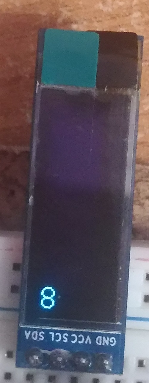
С помощью TheDotFactory создал 1 символ - 8 , но она выводится повернутой на 90 градусов. и повернуть обратно не получается.
Тут возник более интересный вопрос.
В примере всего 5 символов не считая кота . От 1 до 5. Естественно этого мало , и я думаю как добавить новые.
Но не могу понять как они закодированы
- Код:
       0x00, 0x00, 0xF8, 0xF8, 0x98, 0x98, 0x98, 0x98,    //5
      0x18, 0x00, 0x00, 0x00, 0x00, 0x00, 0x0D, 0x19,
      0x19, 0x19, 0x19, 0x1F, 0x0F, 0x00, 0x00, 0x00,
так закодированы все 5 цифр , и куда не залезу такой кодировки нет.
С помощью TheDotFactory создал 1 символ - 8 , но она выводится повернутой на 90 градусов. и повернуть обратно не получается.
Re: SSD1306 128X32
Вс фев 25, 2018 20:19:30
обычно 5 байт на символ, прорисовка столбиками.
Re: SSD1306 128X32
Вт янв 15, 2019 11:18:08
Спасибо други, и у меня заработало!
Вот мой инит
uint8_t init_data[] = {0xAE, 0xA6, 0x20, 0x00, 0x21, 0x00, 0x7F, 0x22, 0x00, 0x07, 0xA1, 0xC8, 0xA8, 0x1F, 0xDA,0x02, 0x81, 0x00, 0x8D, 0x14, 0xAF};
// 0xAE - display off
// 0xA6 - normal (not inversed)
// 0x20, 0x00 - page horizontal adressing mode
// 0x21, 0x00, 0x7F - column address from 0 to 127
// 0x22, 0x00, 0x07 - page address from 0 to 7
// 0xA1 - segment re-map (vertical mirroring)
// 0xC8 - COM scan direction (horizontal mirroring)
// 0xA8, 0x3F - multiplex ratio 128x64============
// 0xA8, 0x1F - 128x32==========
// 0xDA, 0x12 - 128x64==========
// 0xDA, 0x02 - 128x32==========
// 0x81, 0x7F - contrast ratio 127
// 0x8D, 0x14 - enable charge pump
// 0xAF - display on (only just after enabling charge pump)
Вот мой инит
Спойлер
// Initialize LCDuint8_t init_data[] = {0xAE, 0xA6, 0x20, 0x00, 0x21, 0x00, 0x7F, 0x22, 0x00, 0x07, 0xA1, 0xC8, 0xA8, 0x1F, 0xDA,0x02, 0x81, 0x00, 0x8D, 0x14, 0xAF};
// 0xAE - display off
// 0xA6 - normal (not inversed)
// 0x20, 0x00 - page horizontal adressing mode
// 0x21, 0x00, 0x7F - column address from 0 to 127
// 0x22, 0x00, 0x07 - page address from 0 to 7
// 0xA1 - segment re-map (vertical mirroring)
// 0xC8 - COM scan direction (horizontal mirroring)
// 0xA8, 0x3F - multiplex ratio 128x64============
// 0xA8, 0x1F - 128x32==========
// 0xDA, 0x12 - 128x64==========
// 0xDA, 0x02 - 128x32==========
// 0x81, 0x7F - contrast ratio 127
// 0x8D, 0x14 - enable charge pump
// 0xAF - display on (only just after enabling charge pump)
Re: SSD1306 128X32
Пн окт 07, 2019 13:07:54
Не стал плодить темы, пишу сюда.
Нарисовалась у меня проблемка с модулем 128х32 I2C.
Колупаюсь второй день. Вначале думал проблема в моём коде, но по факту пришел к выводу, что проблема в самом модуле.
Итак, по-порядку...
МК - ATtiny45.
Драйвер USI_TWI интерфейса взят из AN AVR310.
Начальные строчки в хидере выглядят так (полный код во-вложении)
Проблема в следующем. При подаче питания МК стартует и работает, согласно кода. Но при этом на дисплее ничего не отображается. Если произвести внешний сброс микроконтроллера, то все отлично выводится на дисплей. Цепь сброса МК содержит подтягивающий резистор 10 кОм, конденсатор 1 мкФ (установлен на случай медленно поднимающегося питания) и диода. Все согласно даташита.
Инициализация дисплея ориентирована именно на индикатор 128х32. Я эти нюансы знаю и даташит имеется.
При этом, если подключаю модуль 128х64, то все прекрасно работает. При чем что в режиме 128х32, что в режиме 128х64. Только в режиме 128х32 изображение выводится через строчку и поэтому выглядит растянутым по вертикали.
У меня только два соображения:
1) либо схема включения отличается и нет какого-то "важного" элемента на модуле 128х32;
2) либо модуль дефектный сам по себе. Но почему тогда он адекватно и стабильно запускается при внешнем сбросе МК без снятия питания, а при подаче питания, наоборот, не запускается?
Модуль бренда DM с маркировкой OLED-091
Есть адрес http://www.diymore.cc
Но инфы я там не нашел. Только ценники на товар.
Предвидя вопросы, добавлю инициализацию для 128х32
Нарисовалась у меня проблемка с модулем 128х32 I2C.
Колупаюсь второй день. Вначале думал проблема в моём коде, но по факту пришел к выводу, что проблема в самом модуле.
Итак, по-порядку...
МК - ATtiny45.
Драйвер USI_TWI интерфейса взят из AN AVR310.
Начальные строчки в хидере выглядят так (полный код во-вложении)
Спойлер
- Код:
// Defines controlling timing limits
#define TWI_FAST_MODE

//max Fck/2
#define SYS_CLK   4000.0  // [kHz]
//#define SYS_CLK   1000.0  // [kHz]     ATtiny2313

#ifdef TWI_FAST_MODE               // TWI FAST mode timing limits. SCL = 100-400kHz
  #define T2_TWI    ((SYS_CLK *1300) /1000000) +1 // >1,3us
  #define T4_TWI    ((SYS_CLK * 600) /1000000) +1 // >0,6us

#else                              // TWI STANDARD mode timing limits. SCL <= 100kHz
  #define T2_TWI    ((SYS_CLK *4700) /1000000) +1 // >4,7us
  #define T4_TWI    ((SYS_CLK *4000) /1000000) +1 // >4,0us
#endif

// Defines controling code generating
//#define PARAM_VERIFICATION
//#define NOISE_TESTING
#define SIGNAL_VERIFY

//USI_TWI messages and flags and bit masks
//#define SUCCESS   7
//#define MSG       0
Проблема в следующем. При подаче питания МК стартует и работает, согласно кода. Но при этом на дисплее ничего не отображается. Если произвести внешний сброс микроконтроллера, то все отлично выводится на дисплей. Цепь сброса МК содержит подтягивающий резистор 10 кОм, конденсатор 1 мкФ (установлен на случай медленно поднимающегося питания) и диода. Все согласно даташита.
Инициализация дисплея ориентирована именно на индикатор 128х32. Я эти нюансы знаю и даташит имеется.
При этом, если подключаю модуль 128х64, то все прекрасно работает. При чем что в режиме 128х32, что в режиме 128х64. Только в режиме 128х32 изображение выводится через строчку и поэтому выглядит растянутым по вертикали.
У меня только два соображения:
1) либо схема включения отличается и нет какого-то "важного" элемента на модуле 128х32;
2) либо модуль дефектный сам по себе. Но почему тогда он адекватно и стабильно запускается при внешнем сбросе МК без снятия питания, а при подаче питания, наоборот, не запускается?
Модуль бренда DM с маркировкой OLED-091
Есть адрес http://www.diymore.cc
Но инфы я там не нашел. Только ценники на товар.
Предвидя вопросы, добавлю инициализацию для 128х32
Спойлер
- Код:
0xAE, // Выключить дисплей

0xD5, // Настройка частоты обновления дисплея
0x80,
///+----- делитель 0-F/ 0 - деление на 1
//+------ частота генератора. по умочанию 0x80
0xA8, // Установить multiplex ratio
0x1F, // 1/64 duty (значение по умолчанию), 0x1F - 128x32, 0x3F - 128x64

0xD3, // Смещение дисплея (offset)
0x00, // Нет смещения

0x40, // Начала строки начала разверки 0x40 с начала RAM

0x8D, // Управление внутреним преобразователем
0x14, // 0x10 - отключить (VCC подается извне) 0x14 - запустить внутрений DC/DC

0x20, // Режим автоматической адресации
0x00, // 0-по горизонтали с переходом на новую страницу (строку)
      // 1 - по вертикали с переходом на новую строку
      // 2 - только по выбранной странице без перехода

0xA1, // Режим разверки по странице (по X)
      // A1 - нормальный режим (слева/направо) A0 - обратный (справа/налево)

0xC8, // Режим сканирования озу дисплея
      // для изменения системы координат
      // С0 - снизу/верх (начало нижний левый угол)
      // С8 - сверху/вниз (начало верний левый угол)
0xDA, // Аппаратная конфигурация COM
0x02, // 0x02 - 128x32, 0x12 - 128x64

0x81, // Установка яркости дисплея
0xСF, // 0x8F..0xCF

0xD9, // Настройка фаз DC/DC преоразователя
0xF1, // 0x22 - VCC подается извне / 0xF1 для внутренего

0xDB, // Установка уровня VcomH
0x40, // Влияет на яркость дисплея 0x00..0x70

0xA4, // Режим нормальный

0xA6, // 0xA6 - нет инверсии, 0xA7 - инверсия дисплея

0xAF  // Дисплей включен
- Вложения
-
- USI_TWI_Master_AVR310.zip
- (4.65 KiB) Скачиваний: 313
Re: SSD1306 128X32
Вт окт 08, 2019 07:51:18
Сегодня удалось взять у кума такой же дисплей 128х32. Мой выполнен на плате с черной маской и маркировкой OLED-091, у кума модуль на синей платке.
Ну и самое интересное, дисплей на синей плате работает как надо. Все-таки проблема в железяке
Ну и самое интересное, дисплей на синей плате работает как надо. Все-таки проблема в железяке
Re: SSD1306 128X32
Вт окт 08, 2019 13:17:23
После включения питания,перед инитом надо подождать...
Re: SSD1306 128X32
Вт окт 08, 2019 15:54:55
После включения питания,перед инитом надо подождать...
Сколько ждать то?
у меня так:
1) подаём питание.
2) контроллер инициализируется +64 мс
3) далее инициализация шины USI (для ATtiny45) c медленной скоростью дабы не было нареканий по таймингам.
4) далее инициализация SSD1306 + очистка дисплея.
5) вывод текста ( не принципиально какого)
Так вот, если между пунктами 3 и 4 поставить задержку хоть 1 секунду, то один фиг дисплей ничего не отобразит.
PS. Я не фанат ардуины, но у меня есть китайская UNO чисто для проверки всяких модулей. Я использовал пример из библиотеки Adafruit. Мне повезло, подобный дисплей 128*32 нашелся у кума. Его вариант выполнен на синей плате, мой на чёрной с маркировкой DM. При подключении дисплеев к UNO поведение такое. Дисплей, взятый у кума, после подачи питания на плату UNO сразу выводит картинку. Мой же дисплей в момент подключения питания ничего не отображает. На плате UNO есть светодиод "L" При подаче питания он мигает и вот когда он тухнет, а потом загорается постоянно, то в этот момент мой дисплей начинает отображать картинку. Я не знаю за что отвечает этот светодиод. Но может кому-то из опытных ардуинщиков такое поведение дисплея на плате UNO что-то подскажет?
Re: SSD1306 128X32
Вт окт 08, 2019 20:17:53
L - обычный светик, подключенный анодом к 13му пину (тот, который 13 на плате ардуины отмечен, а не у МК). Следовательно светится при выводе выского уровня на этот пин. У вас диспл к дуине к каким пинам как подключается?
EDIT: Пишут что в новых унах этот пин не напрямую подключен, а через ОУ. Если пин 13 будет болтаться в HIGH-Z (как он и есть по-умолчанию на INPUT), будет светик мигать. Добавьте в setup() строки:
чтобы он не мигал от наводок.
EDIT: Пишут что в новых унах этот пин не напрямую подключен, а через ОУ. Если пин 13 будет болтаться в HIGH-Z (как он и есть по-умолчанию на INPUT), будет светик мигать. Добавьте в setup() строки:
- Код:
pinMode(13, OUTPUT);
digitalWrite(13, LOW);
чтобы он не мигал от наводок.
Re: SSD1306 128X32
Вт окт 08, 2019 20:46:52
NStorm писал(а):У вас диспл к дуине к каким пинам как подключается?
SDA, SCL, +5V, GND. Я не знаю какие конкретно порты в этой UNO присвоены к SDA, SCL, не разбирался. У меня на китайской плате колодка отдельная разведена для I2C.
NStorm писал(а):Если пин 13 будет болтаться в HIGH-Z (как он и есть по-умолчанию на INPUT), будет светик мигать.
Да уж больно он целенаправленно мигает. Явно идет какой-то вывод информации. Трогать не буду, мне он не мешает.
Заодно хочу уточнить, кто знает. Что делает этот код?
- Код:
#define OLED_RESET 4
Adafruit_SSD1306 display(OLED_RESET);
Хочу понять, каким образом можно сделать RESET контроллера дисплея, если он подключен по шине I2C и вывод RES# подключен к питанию?
Re: SSD1306 128X32
Ср окт 09, 2019 06:48:59
serg_svd, код адафруктов вроде умеет софтовый I2C, на любых пинах, поэтому и спрашивал. Но по инициализации ниже понятно, что вы используете конструктор для железного i2c.
Так сложно 2 строчки для проверки что изменится прописать?
Ответ в доке к либе или в сырцах можно посмотреть описание конструктора:
Видимо для дисплов, где RES# выведен отдельно. Можно смело -1 указать, если его не использовать. Там есть более продвинутый конструктор, можете его попробовать:
Трогать не буду, мне он не мешает.
Так сложно 2 строчки для проверки что изменится прописать?
Хочу понять, каким образом можно сделать RESET контроллера дисплея, если он подключен по шине I2C и вывод RES# подключен к питанию?
Ответ в доке к либе или в сырцах можно посмотреть описание конструктора:
- Код:
/*!
    @brief  DEPRECATED constructor for I2C SSD1306 displays. Provided for
            older code to maintain compatibility with the current library.
            Screen size is determined by enabling one of the SSD1306_* size
            defines in Adafruit_SSD1306.h. New code should NOT use this.
            Only the primary I2C bus is supported.
    @param  rst_pin
            Reset pin (using Arduino pin numbering), or -1 if not used
            (some displays might be wired to share the microcontroller's
            reset pin).
    @return Adafruit_SSD1306 object.
    @note   Call the object's begin() function before use -- buffer
            allocation is performed there!
*/
Adafruit_SSD1306::Adafruit_SSD1306(int8_t rst_pin) :
  Adafruit_GFX(SSD1306_LCDWIDTH, SSD1306_LCDHEIGHT), spi(NULL), wire(&Wire),
  buffer(NULL), mosiPin(-1), clkPin(-1), dcPin(-1), csPin(-1),
  rstPin(rst_pin) {
}
Видимо для дисплов, где RES# выведен отдельно. Можно смело -1 указать, если его не использовать. Там есть более продвинутый конструктор, можете его попробовать:
- Код:
/*!
    @brief  Constructor for I2C-interfaced SSD1306 displays.
    @param  w
            Display width in pixels
    @param  h
            Display height in pixels
    @param  twi
            Pointer to an existing TwoWire instance (e.g. &Wire, the
            microcontroller's primary I2C bus).
    @param  rst_pin
            Reset pin (using Arduino pin numbering), or -1 if not used
            (some displays might be wired to share the microcontroller's
            reset pin).
    @param  clkDuring
            Speed (in Hz) for Wire transmissions in SSD1306 library calls.
            Defaults to 400000 (400 KHz), a known 'safe' value for most
            microcontrollers, and meets the SSD1306 datasheet spec.
            Some systems can operate I2C faster (800 KHz for ESP32, 1 MHz
            for many other 32-bit MCUs), and some (perhaps not all)
            SSD1306's can work with this -- so it's optionally be specified
            here and is not a default behavior. (Ignored if using pre-1.5.7
            Arduino software, which operates I2C at a fixed 100 KHz.)
    @param  clkAfter
            Speed (in Hz) for Wire transmissions following SSD1306 library
            calls. Defaults to 100000 (100 KHz), the default Arduino Wire
            speed. This is done rather than leaving it at the 'during' speed
            because other devices on the I2C bus might not be compatible
            with the faster rate. (Ignored if using pre-1.5.7 Arduino
            software, which operates I2C at a fixed 100 KHz.)
    @return Adafruit_SSD1306 object.
    @note   Call the object's begin() function before use -- buffer
            allocation is performed there!
*/
Adafruit_SSD1306::Adafruit_SSD1306(uint8_t w, uint8_t h, TwoWire *twi,
  int8_t rst_pin, uint32_t clkDuring, uint32_t clkAfter) :
  Adafruit_GFX(w, h), spi(NULL), wire(twi ? twi : &Wire), buffer(NULL),
  mosiPin(-1), clkPin(-1), dcPin(-1), csPin(-1), rstPin(rst_pin),
  wireClk(clkDuring), restoreClk(clkAfter) {
}
Re: SSD1306 128X32
Ср окт 09, 2019 08:50:18
Народ! Спасибо за участие, конечно!
Но порой случается невероятное, и код рабочий. Вот так-то! Проблема, как я сразу и написал в пункте 2, была железнячная.
Короче! Кто купит подобную плату с маркировкой DM и она у вас не взлетит, то я Вам подскажу решение. Производителем на плате тупо на плате поменяны местами 2 резистора. Один по ноге RES#, второй по IREF. В итоге при подаче питание напряжение на RES# через резистор 560 кОм ну очень долго зяряжает конденсатор и, соответственно, слишком вяло нарастает. Осциллографом не смотрел, но и по тестеру это секунды 3-4 точно. Так что вот так!
Перепаял, дисплей заработал как надо
Re: SSD1306 128X32
Ср дек 23, 2020 17:25:28
Скажите пожалуйста, можно ли этот дисплей (шлейф без платы) подключить не по IIC, а по SPI?
Re: SSD1306 128X32
Чт дек 24, 2020 21:32:35
CSOND, можно: https://eax.me/stm32-ssd1306/
Спасибо, статья интересная, но в ней ничего не говорят о 128х32 с 14 pin шлейфом. Описанные модули имеют 30 pin шлейф, который позволяет выбирать интерфейс его распайкой, но вопрос с моим не освещён. скорее всего он только IIC.
- Вложения
-
- OLED 0,91 128x32.jpg
- (19.25 KiB) Скачиваний: 152
Re: SSD1306 128X32
Чт дек 24, 2020 22:10:21
CSOND, понятно, я вопрос не так понял. Думал спрашивается бывают ли они SPI версии. Судя по распиновке на 14-пиновом шлейфе не выведен CS#, а значит SPI режим включить нельзя.
Re: SSD1306 128X32
Пт дек 25, 2020 06:57:09
Примитивный люксметр с датчиком BH1750, с индикацией на дисплей SSD1306 128x32,
https://www.youtube.com/watch?v=xTi-7osjKtc
https://www.youtube.com/watch?v=xTi-7osjKtc