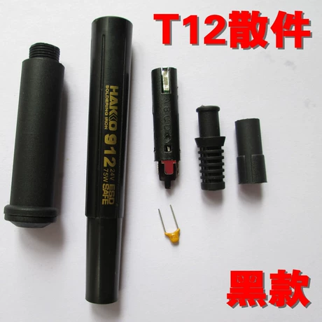
Контроллер паяльника Hakko FM-2028 с энкодером
Вт мар 18, 2014 15:15:12
На нашем сайте разработаны 6(шесть) превосходных паяльных станций.Сам собрал 3 разных - все прекрасно работают.Все 6 станций используют паяльник Hakko-907 или его китайские копии,с его достоинствами (малая стоимость,большой выбор жал,доступность) и недостатками (все про них знают). Давно была мечта приспособить паяльник с монолитным жалом,где нагреватель и жало находятся в одном корпусе.Читая ветку форума (Цифровая паяльная станция своими руками.(V 2.0)) обнаружил что Victor_P. в прошивке 1.4 сделал замеры температуры в паузах нагрева. То что надо.
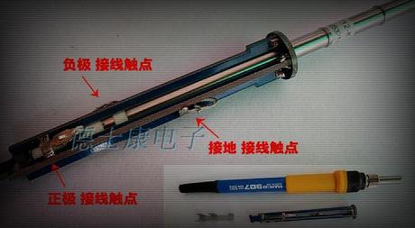
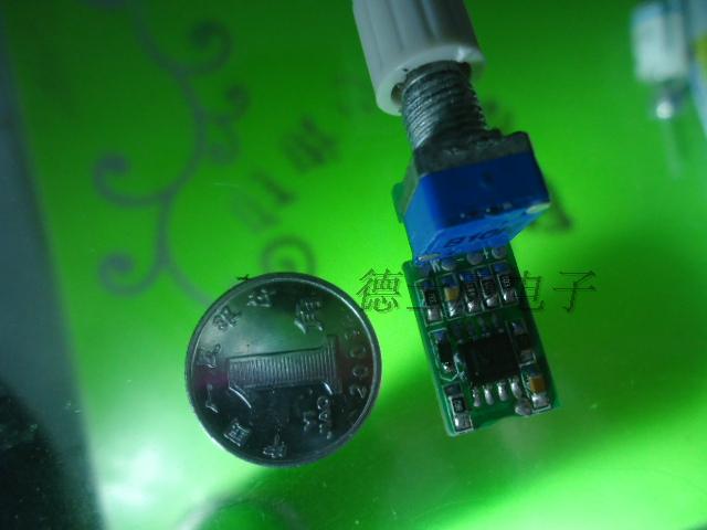
Легкая адаптация схемы Victor_P. позволила подключить паяльник Hakko FM-2028 (вернее его китайскую копию) использующие катриджи Т12 или Т15.Прошивка последняя от Victor_P. 1.42beta ( с этой прошивкой IMHO будет и ржавый гвоздь паять если его правильно запрограмировать).Настройки ПИД следующие Р-10,I-99,D-10,U-95. Температуру с жалом Т12-BCF3 до 280 с учетом софт-старта набирает за 17 секунд,температуру держит плюс-минус 1 градус, при температуре 280 гр при пайке полигона 2 на 3 см просадка составляет 3 ..4 градуса и тут же добирает до 280 ,как только убираю жало от полигона подьем на 2 градуса и тут же возвращение к заданной.Присутствует небольшой забег при нагреве от комнатной(20) до рабочей(280) на 6..7 градусов но в течеении 3 сек приходит в норму.
Легкая адаптация схемы Victor_P. позволила подключить паяльник Hakko FM-2028 (вернее его китайскую копию) использующие катриджи Т12 или Т15.Прошивка последняя от Victor_P. 1.42beta ( с этой прошивкой IMHO будет и ржавый гвоздь паять если его правильно запрограмировать).Настройки ПИД следующие Р-10,I-99,D-10,U-95. Температуру с жалом Т12-BCF3 до 280 с учетом софт-старта набирает за 17 секунд,температуру держит плюс-минус 1 градус, при температуре 280 гр при пайке полигона 2 на 3 см просадка составляет 3 ..4 градуса и тут же добирает до 280 ,как только убираю жало от полигона подьем на 2 градуса и тут же возвращение к заданной.Присутствует небольшой забег при нагреве от комнатной(20) до рабочей(280) на 6..7 градусов но в течеении 3 сек приходит в норму.
- Вложения
-
- IMG_03.jpg
- Foto 3
- (155.63 KiB) Скачиваний: 32965
-
- IMG_02.jpg
- Foto 2
- (224.88 KiB) Скачиваний: 24273
-
- IMG_01.jpg
- Foto 1
- (171.67 KiB) Скачиваний: 19549
-
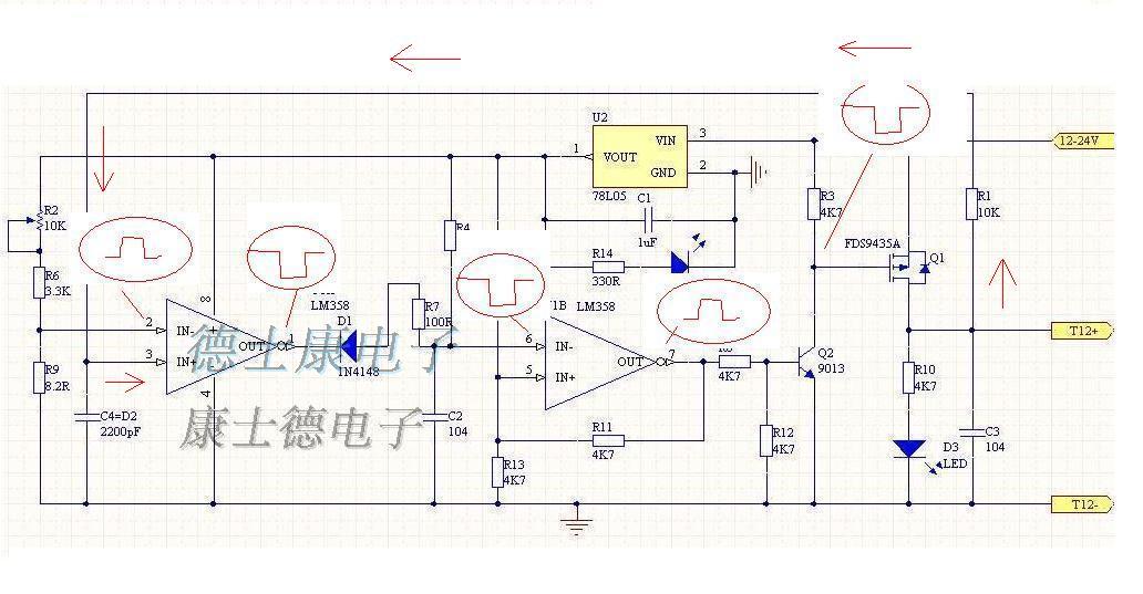
- FM2028_PCB.rar
- ПП
- (46.58 KiB) Скачиваний: 13361
-
- FM-2028.pdf
- Схема
- (120.65 KiB) Скачиваний: 20340
Re: Контроллер паяльника Hakko FM-2028 с энкодером
Пт мар 21, 2014 22:42:56
Странно, неужели никому неинтересна эта тема...  Ведь вещь-то действительно стоящая.
Ведь вещь-то действительно стоящая.
Re: Контроллер паяльника Hakko FM-2028 с энкодером
Вс мар 23, 2014 23:24:49
Наверное все обитают в основной теме...
Re: Контроллер паяльника Hakko FM-2028 с энкодером
Вс мар 23, 2014 23:49:00
Да, тема интересная, у меня паяльник Goot, думаю там тоже, что то похожее можно сделать.
Там тоже стоит термоэлемент, так, что в паузах между нагревом можно попробовать мерить температуру.
Там тоже стоит термоэлемент, так, что в паузах между нагревом можно попробовать мерить температуру.
Re: Контроллер паяльника Hakko FM-2028 с энкодером
Ср апр 16, 2014 13:05:17
Провел поверку всех своих катриджей.Все жала имеют лазерную гравировку HAKKO(похоже на настоящие).
Брал по 250 рублей .
Результат в табличке.
Брал по 250 рублей .
Результат в табличке.
- Вложения
-
- ___12 (1).pdf
- (10.93 KiB) Скачиваний: 6594
Re: Контроллер паяльника Hakko FM-2028 с энкодером
Пт апр 18, 2014 09:41:09
Тема, то интересна, но сказывается небольшая распространенность указанного паяльника. Клоны Hakko-907 в каждом магазине продаются по демократичной цене, а FM-2028 нет, нужно в Китае покупать. А так, то за корпус +. Самодельный с метала не просто на коленке сделать.Муркот писал(а):Странно, неужели никому неинтересна эта тема...
Re: Контроллер паяльника Hakko FM-2028 с энкодером
Пн май 05, 2014 14:31:19
Относительно недавно узнал про жала Т12. Заинтригован. Хочется попробовать. Наверное буду заказывать паяльник у китайцев. Какой лучше взять, разборный FM-2028 или же FX-9051?
PS. кстати добавлю еще пару ссылок со схемами контроллеров к данному типу паяльника с просторов интернета http://radio.aliot.com.ua/?p=945 и http://ired.ucoz.ru/news/kontroller_pajalnika_hakko_fm_2028/2013-09-26-6
Версия прошивки у автора есть уже 1,6. Она не подходит под эту схему?
PS. кстати добавлю еще пару ссылок со схемами контроллеров к данному типу паяльника с просторов интернета http://radio.aliot.com.ua/?p=945 и http://ired.ucoz.ru/news/kontroller_pajalnika_hakko_fm_2028/2013-09-26-6
Версия прошивки у автора есть уже 1,6. Она не подходит под эту схему?
Re: Контроллер паяльника Hakko FM-2028 с энкодером
Пн май 05, 2014 23:58:25
В общем посмотрел некоторые отзывы на ручки для жал Т12 и заказал себе FX-9501. Что-то больше понравилась.
Re: Контроллер паяльника Hakko FM-2028 с энкодером
Вт май 06, 2014 11:04:49
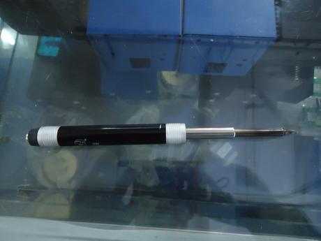
Пользуюсь ручками и FM-2028(часто) и FX-9501(не часто).Нареканий обе не вызывают несмотря на стоимость 12уе и 11уе.
Хотя в сети видел плохие отзывы на FM-2028.Мне наверно повезло.
Прошивка 1.6 полность подходит, сейчас ей и пользуюсь-косяков не обнаружено.Паяльной станцией доволен на 99%.
Хотя в сети видел плохие отзывы на FM-2028.Мне наверно повезло.
Прошивка 1.6 полность подходит, сейчас ей и пользуюсь-косяков не обнаружено.Паяльной станцией доволен на 99%.
- Вложения
-
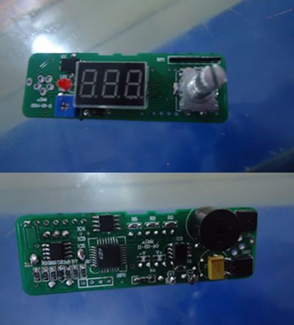
- 09876.jpg
- FM-2028vsFX-9051
- (243.55 KiB) Скачиваний: 9008
Re: Контроллер паяльника Hakko FM-2028 с энкодером
Вт май 06, 2014 14:19:50
BV-Dial писал(а):Паяльной станцией доволен на 99%.
А что входит в 1%?
По поводу ручек, 2028 более удобна для частой смены жал. Причем и наконечник у каждого жала должен быть свой. Но я часто жала менять не планирую. У меня пока желание опробовать данный тип жал, так как люкеевский паяльник не всем нравится.
Если зацепит, то подумаю о покупке 2028. В нем меня смущает сама защелка крепления ручки к сменному наконечнику. Выглядит больно хило. Хотя с другой стороны там то только нагрузка от провода да и все.
Re: Контроллер паяльника Hakko FM-2028 с энкодером
Вт май 06, 2014 16:05:18
У FX-9501 жало меняется быстрее.За защелки у FM-2028В не бойтесь - достаточно крепкие.В 1% входит нелинейность на краях диапазона( на 200 градусах завышение на 10....15 градусов ,на 380 занижение на 10...15 градусах),но это уже мои придирки все равно почти всегда паяю при температурах 260....300 градусах.
После Hakko-907(оригинал) был приятно удивлен.Попытаюсь в ближайшее время видео небольшое записать.
После Hakko-907(оригинал) был приятно удивлен.Попытаюсь в ближайшее время видео небольшое записать.
Re: Контроллер паяльника Hakko FM-2028 с энкодером
Вт май 06, 2014 16:40:11
BV-Dial писал(а):У FX-9501 жало меняется быстрее.
Да нет. Быстрее у 2028.
Я может неправильно деталь называю, но я имел в виду желтый наконечник за который паяльник и держится. По задумке производителя он должен быть на каждом жале. И тогда их можно сменять быстро не дожидаясь остывания жала. Причем эти ручки есть разных цветов
Re: Контроллер паяльника Hakko FM-2028 с энкодером
Вт май 06, 2014 16:53:57
По задумке производителя для замены жала у FM-2028В надо нажать на кнопки-защелки - и жало с половинкой паяльника выходит из синей трубки.Но т.к. у меня не оригинал и кнопки-защелки работают не так как задумал производитель жало меняются тупо вытаскиванием из желтой половины как и у FX-9501.
Re: Контроллер паяльника Hakko FM-2028 с энкодером
Вт май 06, 2014 21:19:01
Очень интересная тема!
Действительно ли T12 удобнее 900М/T18 на практике?
Если да, то хочется повторить Вашу конструкцию.
Но всё упирается в жало… Помогите разобраться, ищу его на taobao:
Ручки, как я понял, также подойдут от Hakko 942 (912)?
Кстати, сами китайцы предлагают адаптировать ручку от Hakko 936 (907), но получается "удочка":

и цельнометаллический вариант:
Какой выбрать?
Кстати, в большом ассортименте аналоговые контроллеры для T12, типа:
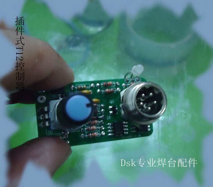
Оно реально работает?
А вот такие контроллеры со звуком (?):
И вот ещё что-то с открытым кодом (скопирую сюда) http://item.taobao.com/item.htm?spm=a1z ... 8575397573
Ещё я смотрю, большинство оттуда питается от ноутбучной зарядки 19В…
Действительно ли T12 удобнее 900М/T18 на практике?
Если да, то хочется повторить Вашу конструкцию.
Но всё упирается в жало… Помогите разобраться, ищу его на taobao:
Ручки, как я понял, также подойдут от Hakko 942 (912)?
Кстати, сами китайцы предлагают адаптировать ручку от Hakko 936 (907), но получается "удочка":
и цельнометаллический вариант:
Какой выбрать?
Кстати, в большом ассортименте аналоговые контроллеры для T12, типа:
Оно реально работает?
А вот такие контроллеры со звуком (?):
И вот ещё что-то с открытым кодом (скопирую сюда) http://item.taobao.com/item.htm?spm=a1z ... 8575397573
Спойлер
- Код:
=====
//----------
// Blinky.c
//----------
// Copyright (C) 2010 德士康电子 Laboratories, Inc.
//
// AUTH: JS
// DATE: 11 JUL 3
//
// This program flashes the green LED on the C8051F31x target board about
// five times a second using the interrupt handler for Timer2.
//
// Target: C8051F31x
//
// Tool chain: KEIL Eval 'c'
//调光OK;
//开关OK;
//24c02ok;
//----------
// Includes
//----------
#include <c8051f310.h> // SFR declarations
#include <INTRINS.H>
#include <stdio.h>
//----------
//----------
sfr16 ADC0 = 0xbd; // ADC0 data
#define INT_DEC 256 // integrate and decimate ratio
long result;//ADC
//----------
// Global CONSTANTS
//----------
#define SYSCLK 24500000 // System clock frequency
#define SMB_FREQUENCY 50000 // Target SCL clock rate
#define WRITE 0x00 // SMBus WRITE command
#define READ 0x01 // SMBus READ command
// Device addresses (7 bits, lsb is a don't care)
#define EEPROM_ADDR 0xA0 // Device address for slave target
// Note: This address is specified
// in the Microchip 24LC02B
// datasheet.
// SMBus Buffer Size
#define SMB_BUFF_SIZE 0x08 // Defines the maximum number of bytes
// that can be sent or received in a
// single transfer
// Status vector - top 4 bits only
#define SMB_MTSTA 0xE0 // (MT) start transmitted
#define SMB_MTDB 0xC0 // (MT) data byte transmitted
#define SMB_MRDB 0x80 // (MR) data byte received
//----------
// Global VARIABLES
//----------
unsigned char* pSMB_DATA_IN; // Global pointer for SMBus data
// All receive data is written here
unsigned char SMB_SINGLEBYTE_OUT; // Global holder for single byte writes
unsigned char* pSMB_DATA_OUT; // Global pointer for SMBus data.
// All transmit data is read from here
unsigned char SMB_DATA_LEN; // Global holder for number of bytes
// to send or receive in the current
// SMBus transfer
unsigned char WORD_ADDR; // Global holder for the EEPROM word
// address that will be accessed in
// the next transfer
unsigned char TARGET; // Target SMBus slave address
unsigned char temp_char;
unsigned char retval;
bit SMB_BUSY = 0; // Software flag to indicate when the
// EEPROM_ByteRead() or
// EEPROM_ByteWrite()
// functions have claimed the SMBus
bit SMB_RW; // Software flag to indicate the
// direction of the current transfer
bit SMB_SENDWORDADDR; // When set, this flag causes the ISR
// to send the 8-bit <WORD_ADDR>
// after sending the slave address
bit SMB_RANDOMREAD; // When set, this flag causes the ISR
// to send a START signal after
// sending the word address
bit SMB_ACKPOLL; // When set, this flag causes the ISR
// to send a repeated START until the
// slave has acknowledged its address
// 16-bit SFR declarations
sfr16 TMR2RL = 0xca; // Timer2 reload registers
sfr16 TMR2 = 0xcc; // Timer2 counter registers
sfr16 TMR3RL = 0x92; // Timer2 reload registers
sfr16 TMR3 = 0x94; // Timer3 counter registers
//----------
// 16-bit SFR Definitions for 'F30x
//----------
int temp_int;
int temp;
unsigned char k;
unsigned int m=200;
unsigned int LD;
unsigned char data1;
unsigned int set_PCA=2;//PCA
unsigned int Sign =0; //标记
unsigned int Sign_dispy =0; //标记
sbit LED = P3^3; // LED='1' means ON // P3.3 - LED
sbit LED1 = P0^7;
sbit key1 = P0^1;//(key_sw)
sbit key2 = P0^2;//(key_up)
sbit key3 = P0^3;//(key_down)2
sbit A3=P1^5;
sbit A2=P1^7;
sbit A1=P1^6;
//sbit A1=P1^5;
//sbit A2=P1^6;
//sbit A3=P1^7;
//----------
///*0,1,2,3,4,5,6,7,8,9,*/
//unsigned char table1[]={0x50,0xDE,0x62,0x46,0xCC,0x45,0x41,0x5E,0x40,0x44,};
unsigned char table1[]={0xA0,0xBE,0xC2,0x8A,0x9C,0x89,0x81,0xBA,0x80,0x88,};
//----------
// Function PROTOTYPES
//----------
void SYSCLK_Init (void);
void PORT_Init (void);
void Timer2_Init (int counts);
void Timer2_ISR (void);
void delay(int time);
unsigned char key_in(void);
void on_off (void);
void pca_up(void);
void display(unsigned char num);
void delay1(unsigned int z);
//----------
void SMBus_Init (void);
void Timer1_Init (void);
void Timer3_Init (void);
void Port_Init (void);
void SMBus_ISR (void);
void Timer3_ISR (void);
void EEPROM_ByteWrite(unsigned char addr, unsigned char dat);
void EEPROM_WriteArray (unsigned char dest_addr, unsigned char *src_addr,
unsigned char len);
unsigned char EEPROM_ByteRead(unsigned char addr);
void EEPROM_ReadArray (unsigned char *dest_addr, unsigned char src_addr,
unsigned char len);
//----------
// SYSCLK_Init
//----------
//
// This routine initializes the system clock to use the internal 24.5MHz / 8
// oscillator as its clock source. Also enables missing clock detector reset.
//
void SYSCLK_Init (void)
{
}
//----------
// PORT_Init
//----------
//
// Configure the Crossbar and GPIO ports.
//
void PORT_Init (void)
{
// P3MDIN = 0xFD;
//------- 24c02-->p1.2_p1.3 ------
//------- PCA-->p1.4 -输出 ------
//P1MDOUT = 0xf0;
// P0SKIP = 0xFF;
// P1SKIP = 0xE3;
// XBR0 = 0x04;
// XBR1 = 0xc1;
//----------
P3MDIN = 0xFD;
P1MDOUT = 0xF0;
P0SKIP = 0xFF;
P1SKIP = 0x03;
XBR0 = 0x04;
XBR1 = 0xC1;
}
//----------
// ADC0配置,T3定时启动ADC
//----------
void ADC0_Init (void)
{
//----------
REF0CN = 0x0e; // 启用内部基准源
//选择采样输入源GND作为负输入ADC工作在单端方式
//ADC0CN = 0xC5;
AMX0P = 0x11;
AMX0N = 0x1F;
ADC0CN = 0xC1; //控制器 0
EIE1 |= 0x08; // 启用 ADC 中断
}
//----------
// ----Timer0_Init----
//----------
void Timer0_Init()
{
TMOD = 0x21; // Mode set -timer 0, -timer 1, = 100001
TH0=0xF0; /* 计数初值写入TH1 */
TL0=0x00; /* 写入计数初值到TL1 */
ET0=1; /* 定时器0中断允许*/
TR0=1; //* 定时器0准备开始 *///Enable Timer 0 Interrupt.
}
//----------
// Timer2_Init
//----------
//
// Configure Timer2 to 16-bit auto-reload and generate an interrupt at
// interval specified by <counts> using SYSCLK/48 as its time base.
//
void Timer2_Init (int counts)
{
TMR2CN = 0x00; // Stop Timer2; Clear TF2;
// use SYSCLK/12 as timebase
CKCON &= ~0x60; // Timer2 clocked based on T2XCLK;
TMR2RL = -counts; // Init reload values
TMR2 = 0xffff; // set to reload immediately
ET2 = 1; // enable Timer2 interrupts
TR2 = 1; // start Timer2
}
//
//----------
//
//----------
void PCA_Init (void)
{
// PCA0CN = 0x40; // PCA0CN:PCA 控制寄存器 允许 PCA计数器/定时器。SFR地址:0xD8
// PCA0MD &= ~0x40;
// PCA0MD = 0x01; // PCA0MD:PCA 方式寄存器 当CF(PCA0CN.7)被置位时,允许PCA 计数器/定时器溢出的中断请求。
// PCA0CPM0 = 0x4b; // { PCA0CPMn:PCA 捕捉/比较寄存器 } MATn=1,PWMn=1,ECCFn=1,
PCA0CN = 0x40;
PCA0CPM0 = 0xc2;
PCA0CPL0 = 0x00;
PCA0CPH0 = 0x00;
PCA0CPL4 = 0x00;
PCA0MD &= 0x40;
PCA0MD = 0x01;
}
//----------
//
//----------
void delay(int time)
{
int a=time;
while(a!=0)
{
a--;
}
}
//----------
//
//----------
void delay1(unsigned int z)
{
unsigned x,y;
for(x=z;x>0;x--)
for(y=114;y>0;y--);
} //z=1为1ms,z=100为100ms,
//----------
//
//----------
unsigned char key_in(void)
{
if(key1==0) //(key_sw) key1=P0^2;
{
key1=1;
delay1(10);
if(key1==0)
{
key1=1;
delay1(10);
while(key1==0);
return(0x1);//返回字符"1"表示按键SW1按下
}
}
//----------
if(key2==0) //(key_up)key2=P2^7;
{
key2=1;
delay1(10);
if(key2==0)
{
key2=1;
delay1(10);
while(key2==0);
if(key3==1)
{
return(0x3);//返回字符"2"表示按键SW1按下
}
return(0x2);//返回字符"2"表示按键SW1按下
}
}
return(0);//返回0,表示没有按键按下
}
//----------
//
//----------
void on_off (void) //
{
if(k==1) //(key_sw) key1=P0^2;
{ Sign = Sign+1;
if (Sign==1)// if/ else 选择结构
{
LED = 0;
}
else if(Sign==2)
{
LED = 1;
Sign= 0;
}
}
}
//----------
//
//----------
void pca_up(void)
{
if(k==2)
{ Sign_dispy=500;
{if (Sign==1)// if/ else 选择结构
m=m-2;
for(;m>400;m=400); //显示匹配的问题
for(;m<200;m=200); //显示匹配的问题
// Write the value 0xCC to location 0x38 in the EEPROM
EEPROM_ByteWrite(0x27, m);
}
}
}
//----------
//
//----------
void pca_down(void)
{
if(k==3)
{ Sign_dispy=500;
{if (Sign==1)// if/ else 选择结构
m=m+2;
for(;m>400;m=400); //显示匹配的问题
for(;m<200;m=200); //显示匹配的问题
// Write the value 0xCC to location 0x38 in the EEPROM
EEPROM_ByteWrite(0x27, m);
}
}
}
//----------
//----------
void display(unsigned int num)
{
unsigned int k,m,n,i;
k=num/1000;
m=(num%1000)/100;
n=(num%100)/10;
i=num%10;
if (Sign==1)// on_display
{
P2=table1[m];
A1=1;
delay1(3);
A1=0;
P2=0xff;
P2= table1[n];
A2=1;
delay1(3);
A2=0;
P2=0xff;
P2=table1[i];
A3=1;
delay1(3);
A3=0;
P2=0xff;
}
else if(Sign==2) // off_display
{
A1=0;
A2=0;
A3=0;
}
}
//----------
//----------
void EEPROM_ByteWrite( unsigned char eaddr, unsigned char edat )
{
while (SMB_BUSY); // Wait for SMBus to be free.
SMB_BUSY = 1; // Claim SMBus (set to busy)
// Set SMBus ISR parameters
TARGET = EEPROM_ADDR; // Set target slave address
SMB_RW = WRITE; // Mark next transfer as a write
SMB_SENDWORDADDR = 1; // Send Word Address after Slave Address
SMB_RANDOMREAD = 0; // Do not send a START signal after
// the word address
SMB_ACKPOLL = 1; // Enable Acknowledge Polling (The ISR
// will automatically restart the
// transfer if the slave does not
// acknowledge its address.
// Specify the Outgoing Data
WORD_ADDR = eaddr; // Set the target address in the EEPROM's
// internal memory space
SMB_SINGLEBYTE_OUT = edat; // store dat (local variable) in a global
// variable so the ISR can read it after
// this function exits
pSMB_DATA_OUT = &SMB_SINGLEBYTE_OUT; // The outgoing data pointer points to
// the <dat> variable.
SMB_DATA_LEN = 1; // Specify to ISR that the next transfer
// will contain one data byte
// Initiate SMBus Transfer
STA = 1;
}
//----------
// EEPROM_WriteArray ()
//----------
// Writes <len> data bytes to the EEPROM slave specified by the <EEPROM_ADDR>
// constant.
//
void EEPROM_WriteArray (unsigned char dest_addr, unsigned char* src_addr,
unsigned char len)
{
unsigned char i;
unsigned char* pData = (unsigned char*) src_addr;
for( i = 0; i < len; i++ ){
EEPROM_ByteWrite(dest_addr++, *pData++);
}
}
//----------
// EEPROM_ByteRead ()
//----------
//
// This function returns a single byte from location <addr> in the EEPROM then
// polls the <SMB_BUSY> flag until the read is complete.
//
unsigned char EEPROM_ByteRead( unsigned char daddr)
{
unsigned char retval; // Holds the return value
while (SMB_BUSY); // Wait for SMBus to be free.
SMB_BUSY = 1; // Claim SMBus (set to busy)
// Set SMBus ISR parameters
TARGET = EEPROM_ADDR; // Set target slave address
SMB_RW = WRITE; // A random read starts as a write
// then changes to a read after
// the repeated start is sent. The
// ISR handles this switchover if
// the <SMB_RANDOMREAD> bit is set.
SMB_SENDWORDADDR = 1; // Send Word Address after Slave Address
SMB_RANDOMREAD = 1; // Send a START after the word address
SMB_ACKPOLL = 1; // Enable Acknowledge Polling
// Specify the Incoming Data
WORD_ADDR = daddr; // Set the target address in the EEPROM's
// internal memory space
pSMB_DATA_IN = &retval; // The incoming data pointer points to
// the <retval> variable.
SMB_DATA_LEN = 1; // Specify to ISR that the next transfer
// will contain one data byte
// Initiate SMBus Transfer
STA = 1;
while(SMB_BUSY); // Wait until data is read
return retval;
}
///////////////
//----------
// EEPROM_ReadArray ()
//----------
// Reads up to 256 data bytes from the EEPROM slave specified by the <EEPROM_ADDR>
// constant.
//
void EEPROM_ReadArray (unsigned char* dest_addr, unsigned char src_addr,
unsigned char len)
{
while (SMB_BUSY); // Wait for SMBus to be free.
SMB_BUSY = 1; // Claim SMBus (set to busy)
// Set SMBus ISR parameters
TARGET = EEPROM_ADDR; // Set target slave address
SMB_RW = WRITE; // A random read starts as a write
// then changes to a read after
// the repeated start is sent. The
// ISR handles this switchover if
// the <SMB_RANDOMREAD> bit is set.
SMB_SENDWORDADDR = 1; // Send Word Address after Slave Address
SMB_RANDOMREAD = 1; // Send a START after the word address
SMB_ACKPOLL = 1; // Enable Acknowledge Polling
// Specify the Incoming Data
WORD_ADDR = src_addr; // Set the target address in the EEPROM's
// internal memory space
pSMB_DATA_IN = (unsigned char*) dest_addr;// Set the the incoming data pointer
SMB_DATA_LEN = len; // Specify to ISR that the next transfer
// will contain <len> data bytes
// Initiate SMBus Transfer
STA = 1;
while(SMB_BUSY); // Wait until data is read
}
//----------
// Initialization Routines
//----------
//----------
// SMBus_Init()
//----------
//
// SMBus configured as follows:
// - SMBus enabled
// - Slave mode disabled
// - Timer1 used as clock source. The resulting SCL frequency will be approximately
// 1/3 the Timer1 overflow rate
// - Setup and hold time extensions enabled
// - Free and SCL low timeout detection enabled
//
void SMBus_Init (void)
{
SMB0CF = 0x5D; // Use Timer1 overflows as SMBus clock
// source;
// Disable slave mode;
// Enable setup & hold time extensions;
// Enable SMBus Free timeout detect;
// Enable SCL low timeout detect;
SMB0CF |= 0x80; // Enable SMBus;
}
//----------
// Timer3_Init()
//----------
//
// Timer3 configured for use by the SMBus low timeout detect feature as follows:
// - Timer3 in 16-bit auto-reload mode
// - SYSCLK/12 as Timer3 clock source
// - Timer3 reload registers loaded for a 25ms overflow period
// - Timer3 pre-loaded to overflow after 25ms
// - Timer3 enabled
//
void Timer3_Init (void)
{
TMR3CN = 0x00; // Timer3 configured for 16-bit
// auto-reload,
// low-byte interrupt disabled
TMR3 = -(SYSCLK/12/40); // Timer3 configured to overflow after
TMR3RL = -(SYSCLK/12/40); // ~25ms (for SMBus low timeout detect)
CKCON &= ~0x40; // Timer3 uses SYSCLK/12
TMR3 |= 0x04; // Start Timer3
}
//----------
// Timer1_Init()
//----------
//
// Timer1 configured as the SMBus clock source as follows:
// - Timer1 in 8-bit auto-reload mode
// - SYSCLK / 12 as Timer1 clock source
// - Timer1 overflow rate => 3 * SMB_FREQUENCY
// - The maximum SCL clock rate will be ~1/3 the Timer1 overflow rate
// - Timer1 enabled
//
void Timer1_Init (void)
{
CKCON &= ~0x0B; // Timer1 clock source = SYSCLK / 12
TMOD = 0x20; // Timer1 in 8-bit auto-reload mode
TH1 = -(SYSCLK/SMB_FREQUENCY/12/3); // Timer1 configured to overflow at 1/3
// the rate defined by SMB_FREQUENCY
TL1 = -(SYSCLK/SMB_FREQUENCY/12/3); // Timer1 preloaded to overflow at 1/3
// the rate defined by SMB_FREQUENCY
TR1 = 1; // Timer1 enabled
}
//----------
// SMBus Interrupt Service Routine (ISR)
//----------
//
// SMBus ISR state machine
// - Master only implementation - no slave or arbitration states defined
// - All incoming data is written starting at the global pointer <pSMB_DATA_IN>
// - All outgoing data is read from the global pointer <pSMB_DATA_OUT>
//
void SMBus_ISR (void) interrupt 7
{
bit FAIL = 0; // Used by the ISR to flag failed
// transfers
static char i=0; // Used by the ISR to count the
// number of data bytes sent or
// received
static bit SEND_START = 0; // Send a start
switch (SMB0CN & 0xF0) // Status vector
{
// Master Transmitter/Receiver: START condition transmitted.
case SMB_MTSTA:
SMB0DAT = TARGET; // Load address of the target slave
SMB0DAT |= SMB_RW; // Load R/W bit
STA = 0; // Manually clear START bit
i = 0;
_nop_(); // reset data byte counter
break;
// Master Transmitter: Data byte (or Slave Address) transmitted
case SMB_MTDB:
if (ACK) // Slave Address or Data Byte
{ // Acknowledged?
if (SEND_START)
{
STA = 1;
SEND_START = 0;
break;
}
if(SMB_SENDWORDADDR) // Are we sending the word address?
{
SMB_SENDWORDADDR = 0; // Clear flag
SMB0DAT = WORD_ADDR; // send word address
if (SMB_RANDOMREAD)
{
SEND_START = 1; // send a START after the next ACK cycle
SMB_RW = READ;
}
break;
}
if (SMB_RW==WRITE) // Is this transfer a WRITE?
{
if (i < SMB_DATA_LEN) // Is there data to send?
{
SMB0DAT = *pSMB_DATA_OUT; // send data byte
pSMB_DATA_OUT++; // increment data out pointer
i++; // increment number of bytes sent
}
else
{
STO = 1; // set STO to terminte transfer
SMB_BUSY = 0; // clear software busy flag
}
}
else {} // If this transfer is a READ,
// then take no action. Slave
// address was transmitted. A
// separate 'case' is defined
// for data byte recieved.
}
else // If slave NACK,
{
if(SMB_ACKPOLL)
{
STA = 1;
// Restart transfer
}
else
{
FAIL = 1; // Indicate failed transfer
} // and handle at end of ISR
}
break;
// Master Receiver: byte received
case SMB_MRDB:
if ( i < SMB_DATA_LEN ) // Is there any data remaining?
{
*pSMB_DATA_IN = SMB0DAT; // Store received byte
pSMB_DATA_IN++; // Increment data in pointer
i++; // Increment number of bytes received
ACK = 1; // Set ACK bit (may be cleared later
// in the code)
}
if (i == SMB_DATA_LEN) // This is the last byte
{
SMB_BUSY = 0; // Free SMBus interface
ACK = 0; // Send NACK to indicate last byte
// of this transfer
STO = 1; // Send STOP to terminate transfer
}
break;
default:
FAIL = 1; // Indicate failed transfer
// and handle at end of ISR
break;
}
if (FAIL) // If the transfer failed,
{
SMB0CN &= ~0x40; // Reset communication
SMB0CN |= 0x40;
SMB_BUSY = 0; // Free SMBus
}
SI=0; // clear interrupt flag
}
//----------
// Timer3 Interrupt Service Routine (ISR)
//----------
//
// A Timer3 interrupt indicates an SMBus SCL low timeout.
// The SMBus is disabled and re-enabled here
//
void Timer3_ISR (void) interrupt 14
{
SMB0CN &= ~0x40; // Disable SMBus
SMB0CN |= 0x40; // Re-enable SMBus
TMR3CN &= ~0x80; // Clear Timer3 interrupt-pending flag
}
//===pca - adc======
unsigned int consequence( int temp,unsigned int m)
{
int tempera;
unsigned int setting_pca;
unsigned int consequence;
tempera=temp;
setting_pca=m;
if( tempera > setting_pca){consequence=255;} //关
else
{ consequence=8; } //开
if( tempera> 380){consequence=255;} //关
if( Sign==0){consequence=255;} //关
return consequence;
}
///----------
//----------
/*
int pid ( )
{
//---------
//定义变量
float Kp; //PI调节的比例常数
float Ti; //PI调节的积分常数
float T; //采样周期
float Ki;
float Kd;
float ek; //偏差e[k]
float ek1; //偏差e[k-1]
float ek2; //偏差e[k-2]
float uk; //u[k]
signed int uk1; //对u[k]四舍五入取整
Kp=200;
Ki=3/2;
ek=temp_int ;
ek1=200;
ek2=ek-ek1;
//Ti= (Ki*ek2)+( Kp*ek);
Ti= (Ki*ek2)+( Kp);
}
*/
//======
//
//----------
// MAIN Routine
//----------
void main (void)
{
// -----初始化-----
int iNum = 0;
int temperature;
char in_buff[8] = {0}; // incoming data buffer
char out_buff[8] = "ABCDEFG"; // outgoing data buffer
PCA0MD &= ~0x40; // WDTE = 0 (clear watchdog timer
// enable)
SYSCLK_Init (); // Initialize system clock to
// 24.5MHz
OSCICN |= 0x03; // Set internal oscillator to highest
// setting (24500000)
RSTSRC = 0x04; // enable missing clock detector
PORT_Init (); // initialize crossbar and GPIO
//-------ADC----------------
Timer0_Init();
ADC0_Init (); // init ADC
AD0TM=0;
//------PCA-------
Timer2_Init (6000); //5000-50000 //Init Timer2 to generate
// interrupts at a 10Hz rate.
PCA_Init (); /*PCA初始化成8位脉宽调置方式*/
//--------24co2--------------
Timer1_Init (); // Configure Timer1 for use as SMBus
// clock source
Timer3_Init (); // Configure Timer2 for use with SMBus
// low timeout detect
SMBus_Init (); // Configure and enable SMBus
//----------
EIE1 = 0x99;
EIP1 = 0x01;
//(PCA0)中断允许
//----------
EA = 1; // enable global interrupts
Sign =1;
// Write the value 0xAA to location 0x25 in the EEPROM
EEPROM_ByteWrite(0x26, 0x1);
// Read the value at location 0x25 in the EEPROM
temp_char = EEPROM_ByteRead(0x26);
// Store the outgoing data buffer at EEPROM address 0x50
EEPROM_WriteArray(0x50, out_buff, sizeof(out_buff));
// Fill the incoming data buffer with data starting at EEPROM address 0x50
EEPROM_ReadArray(in_buff, 0x50, sizeof(in_buff));
//----------
// Read the value at location 0x25 in the EEPROM
temp_char = EEPROM_ByteRead(0x27);
m=temp_char;
//----------
temp_char = EEPROM_ByteRead(0x27);
m=350;
//----------
while(result==0); //等于0,侧等待
while (1) {
EA =0;
// 关中断
temperature = result;
temperature &=0x000fff;
delay1(10);
EA = 1;
temperature = temperature*100L*3/512;
temp_int = temperature; //adc temp_int
temp =temp_int;
//temp =((temp_int-200)*200/100)+200;
set_PCA=consequence(temp, m);
//----------
data1=key_in();
k=data1;
on_off() ; //开关
pca_up(); //PCA加
pca_down(); //PCA减
//----------
}
}
//////////////////////////////////////////////////////////////////
//
//----------
// ---interrupt----
//---------Timer0_Overflow()----------
void Timer0_Overflow() interrupt 1 using 0
{
TH0=0x80;
TL0=0x00;//计数初值到TL0 */
}
//----------
// Timer2_ISR
//----------
//
// This routine changes the state of the LED whenever Timer2 overflows.
//
void Timer2_ISR (void) interrupt 5
{
if (Sign_dispy >= 1) { display(m); Sign_dispy--; }
if (Sign_dispy<=1) { display( temp ); } //显示
TF2H = 0; // clear Timer2 interrupt flag
}
//----------
// ADC0采样中断
//----------
void ADC0_ISR (void) interrupt 10
{
static unsigned int_dec=INT_DEC;
static long accumulator=0L;
ADC0CN &= ~0x20; // 清 ADC 中断标志位
accumulator += ADC0; // 累加ADC采样数据
int_dec--; // 指针减1
if (int_dec == 0)
{ // 累加完了吗?
int_dec = INT_DEC; // 指针复位
result = accumulator>>8;
accumulator = 0L; // 累加和变量清0
}
}
//----------
// Interrupt Service Routines
//----------
//
void PCA_ISR (void) interrupt 11//PCA
{
unsigned char a ;
bit PWM_PAC;
CF = 0;
PCA0CPH0=set_PCA;
}
//================PCA==========
Ещё я смотрю, большинство оттуда питается от ноутбучной зарядки 19В…
Последний раз редактировалось ibiza11 Пт июн 27, 2014 13:48:47, всего редактировалось 1 раз.
Причина: уменьшил картинку
Причина: уменьшил картинку
Re: Контроллер паяльника Hakko FM-2028 с энкодером
Вт май 06, 2014 22:29:05
Китайцы известные пройдохи. Они сами же 2028 скопировали и ляпов понаделали с нормально не нажимающимися фиксаторами и не влезающим жалом. Я отчасти поэтому тоже взял 9051, а не 2028 ручку.
А по поводу питания от 19В - почему бы и нет. Можно хоть от 12в. Только греться дольше будет и не будет отдавать заявленную мощность.
А по поводу питания от 19В - почему бы и нет. Можно хоть от 12в. Только греться дольше будет и не будет отдавать заявленную мощность.
Re: Контроллер паяльника Hakko FM-2028 с энкодером
Вт май 06, 2014 22:33:59
001 писал(а):Ручки, как я понял, также подойдут от Hakko 942 (912)?
о как! а я искал на официальном сайте ручку 9051 и не находил, а она оказывается вон как обзывается
Re: Контроллер паяльника Hakko FM-2028 с энкодером
Вт май 06, 2014 23:44:14
Ребят, тоже интересует этот паяльник, но не нравится то что у китайцев на картриджах плавают параметры,
вот из-за этого плывет калибровка:
У Goot RX802AS картриджы разнесены по группам, т.е на картридже нанесена калибровочная константа, которую
нужно вводить в настройки при смене жала, под группами понимается вот что:

Вот это будет правильно и точно...проверено лично на своем Goot
вот из-за этого плывет калибровка:
BV-Dial писал(а):В 1% входит нелинейность на краях диапазона( на 200 градусах завышение на 10....15 градусов ,на 380 занижение на 10...15 градусах),но это уже мои придирки все равно почти всегда паяю при температурах 260....300 градусах.
У Goot RX802AS картриджы разнесены по группам, т.е на картридже нанесена калибровочная константа, которую
нужно вводить в настройки при смене жала, под группами понимается вот что:

Вот это будет правильно и точно...проверено лично на своем Goot
Re: Контроллер паяльника Hakko FM-2028 с энкодером
Вт май 06, 2014 23:49:12
Т.е. не время переходить с китайских Хакка 900 (они вроде со всех сторон знакомы уже) на T12?
Ну так какую из них брать?
serg_svd писал(а):001 писал(а):Ручки, как я понял, также подойдут от Hakko 942 (912)?
о как! а я искал на официальном сайте ручку 9051 и не находил, а она оказывается вон как обзывается
Ну так какую из них брать?
Re: Контроллер паяльника Hakko FM-2028 с энкодером
Ср май 07, 2014 08:46:25
Для паяльника Hakko 912 применяются жала серии Т2 они на 25мм короче жал Т12.
Re: Контроллер паяльника Hakko FM-2028 с энкодером
Ср май 07, 2014 08:56:20
001 писал(а):Т.е. не время переходить с китайских Хакка 900 (они вроде со всех сторон знакомы уже) на T12?
Ну так какую из них брать?
Я думаю переходить надо. Во всяком случае попробовать самому и решить. Но мне кажется Т12 будет лучше 900 серии. В последней есть существенный недостаток - воздушный зазор между жалом и нагревателем и из-за этого большая тепловая инерция. При пайке мелких деталей впрочем незаметно. На это видимо производитель и рассчитывал. Но вот на массивных деталях этот минус чувствуется реально.
Я недавно отпаивал разъем с LiPO аккумулятора с проводом AWG10. Паяльник 900 серии никак не мог разогреть припой, температуру я задрал, жало обгорать начало даже. Отпаял как только поддул феном 230 градусов на место пайки. Второй разъем отпаял без проблем ЭПСН40 с медным жалом.
Поэтому лично я и хочу проверить Т12.